• I want to thank all the members that have upgraded your accounts. I truly appreciate your support of the site monetarily. Supporting the site keeps this site up and running as a lot of work daily goes on behind the scenes. Click to Support Signs101 ...

Print head - up close and personal

96XP

New Member
My print quality has recently begun to degrade to a point where it was noticeable to me, and to no avail, I tried a whole bunch of things to correct it and made the following discovery.
*And if I have miscalculated, it's because I don't fully know what I'm doing and have a need to better understand. Therefore, this post may require some editing , and definitely some input.


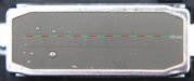
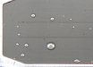
Per the attached image, I had to put on a few macro lenses to capture that which I could not see with the naked eye.
I had a couple minor head strikes over time and thought to myself when it happened, "Oh, what's a hole or two out of a thousand, right?"

To my discovery, there are but a few (50?), and in what should be a straight line, and each of them matter considerably.
Therefore, we can't afford to have any clogging or damage as those few microscopic holes have an entire print to produce.
And if the finished work is ever to be examined up close, the imperfections will be an obvious disgrace.

Now I'm not sure if my head had degraded prematurely due to changing over to Red Giant ink about a year ago, or if it is just normal wear.
And not knowing for certain if print head 1 is the black, I'm posting all the shot counts in hopes someone might have opinion on both the ink and if the shot count is indicative of normal wear at this point.

SHOT COUNTS (Kshots) SP-300V
#1- 1562210
#2- 1744631
#3- 3744553
#4- 2887851


In summary, I have much more respect for what that little print head does and will be much more careful in the times ahead.
Thanks for looking :smile:
 

Attachments

  • FCT-A.jpg
    FCT-A.jpg
    157.5 KB · Views: 232

96XP

New Member
Here attached is a super close-up which has been cropped due to size.
 

Attachments

  • FCT-ZOOM.jpg
    FCT-ZOOM.jpg
    188.3 KB · Views: 167
  • FCT-B.jpg
    FCT-B.jpg
    183.1 KB · Views: 225

artbot

New Member
this is very interesting.

i too have been having issues with overspray. one thing though. i put in a new head, same thing. figured i'd blame the ink, so i printed some tests by simply printing cleaning solution on to clear polyester, same thing. so it may be clogs, or it may be some kind of voltage issue coming upstream. otherwise a brand new head printing pigmentless fluid should do fine.

i'd also do some tests at different resolutions especially playing with variable vs non-variable rips. i've noticed that the non-variable fine dots are the ones that overspray, the regular ones fire perfect.
 

96XP

New Member
Re: "i put in a new head, same thing"
Did your test print turn out clearer than that in my post?
Don't know about voltage upstream being part, however we've had a lot of static last week and I was discharging on just about anything I touched. That had me concerned for the computers as well, though all was good. -But one monitor reboots itself each time I touch the rack (metal) that another system is sitting in and is grounded. Arg.

I tried diff resolutions and profiles, however the results (in terms of clarity) didn't change. And for the heck of it, I cleaned the encoder and optic eye as well.

Not sure if I'm understanding clearly about 'non-variable'. I'm not lazy, and have done a lot of reading, however endless as it sometimes seems, would you mind helping me understand variable vs non-variable better? (the non-variable fine dots are the ones that overspray, the regular ones fire perfect) That has me confused.

Many thanks for the post :smile:
 

artbot

New Member
back in the day (dx2 days) all of the dots were the same same size. it was just called a dot. then variable dots came into the picture. ...your head could print a speck of black up to a big dot of black (...the term used in grand format heads is "grayscale head").

still printers are faster running non-variable profiles. they don't have to pace themselves by calculating all the different dots. in my rip canned profiles are marked as ...720x720VD or 36x720ND showing that this file will be a bit quicker because of the simple dithering vs finer dithering.

as far as running different resolutions, you could run 50 different variable dot profiles of different resolutions and get the overspray (at least that is the case on my printer). what you would want to determine is comparing NV vs VD profiles. for the "NV" profiles, i get no overspray.

also i have a file i made called "encoder test". its a 1" x 60" file of single pixel vertical lines. i have a grayscale black one and a cmyk (each channel touching the next so it's four pixels wide). this is the best test for a quick "encoder check". you print the file and with a loop see if the colors are lined up and listing at all to the right. listing right means dirt, listing left can only mean encoder sensor is going bad because it's impossible to "add" length, just not see it thus needing to travel past the y = 0 into a negative margin (y = -*.**).

my tests with the brand new head look very similar to your hi res scans.
 

96XP

New Member
Brilliant info.
This problem just came about roughly a week ago. I have a new encoder sensor in stock, and a fresh encoder strip on the way. So I'm wondering if I were to swap them out if this may be of benefit, or a waste of time. To note, I've used this particular printer for 4 years now, so in a way, I can't complain much as it has been extremely efficient.
Would you post a segment of your encoder test strip, say 1" x 2" so that I can clone it into a full?
 

artbot

New Member
you can see they are really simple test patterns. if these patterns are perfectly vertical over and over again. ...then your strip and sensor are operating perfectly. the sensor is universal. it can only send a position to the main board. so whatever it does, will occur in all channels. and proof that nothing is wrong is this pattern repeating itself.
 

Attachments

  • encoder test color.jpg
    encoder test color.jpg
    4.8 KB · Views: 177
  • grayscale encoder.jpg
    grayscale encoder.jpg
    3.8 KB · Views: 176
I'm betting that if you park the print carriage to the far left and use a dental mirror and a flashlight, you'll find scratches or scuffing on the black head.
 

96XP

New Member
I'm betting that if you park the print carriage to the far left and use a dental mirror and a flashlight, you'll find scratches or scuffing on the black head.

Hmmm, think I'll try that too.
Maybe with a larger tilted mirror and the camera. I'll snap the reflection and see what condition it's in.
:thankyou:
 

96XP

New Member
I don't know how to make sense of this, but my printer has been printing like as if it were brand new over the past couple or so days. Mind you, I haven't run a print lately where red meets black, however, all other transitions are hair splitting sharp, no banding, not a stray mark.
(It didn't print as clear even after the head soak. ????)

I casually mentioned at one point that there was a lot of static in here, whereby from one second to another, anything I touched that was grounded zapped.

Is there any possibility that phantom static can cause such grief?

Bewildered.
 

rmcginn

New Member
Do a search for: NJ800/KODAK 4800 SERIES TECHNICAL BULLETIN 5

Printer Grounding, ESD Control and Output Symptoms.

2. Ink Overspray
Ink Overspray and/or combination of
data shift and ink overspray is
observed. Normally occurs at severe
ground fault locations (high levels of
AC riding on ground/neutral lines or
high levels of ESD are coming from
the air plenum).
 

96XP

New Member
Thanks for the post, and this is where I read from:

http://www.wideformat.kodak.com/sup...4800 Series Technical Bulletin 5_12072005.pdf

I'll do a check on all the cables and power bars to see where things are at. Pretty sure I gave it the best when I setup, but maybe someone could have swapped one out for another.

Q:
I haven't replaced the dampers in a few years and have a couple news ones arriving later today.
The PDF I printed out covering head change doesn't offer much in regards to the step by step process of changing the dampers, but says the following:

"9. Remove the damper plate and remove the two ink dampers from the head which will be replaced. Do not hold both sides of the ink damper so hard. It should break. Be sure to remove and fix the ink damper with the head board cover fixed. It prevents the ink from dropping on the head board.

10. Remove the head board cover (the transparent cover).

11. Disconnect the 2 flexible cables from the head.

12. Remove the spring, and remove the 3 screws fixing the head in order as shown in the figure. Then, pull the head towards the front and pull it up to remove it."


What I miss seeing/reading is the finer details.
IE.:
1) Is there an order to disconnecting the feed lines from the damper? (inlet first, outlet first, doesn't matter)

2) Will air get into the feed line and what to do if anything?

3) If I'm not replacing the head at this present time and just the dampers, will air get into the head once the old one is removed, and if so, what to do? (prime head?)

4) Should the dampers be primed (loaded) with ink prior to installation, during the installation, or does it take care of itself?

5) How messy is this process? Do I need to protect the carpet and also wear gloves?

*If hind sight is 20/20, then having an understanding beforehand is prudent.
 

artbot

New Member
way easier than it sounds. unhook each damper in any order. pull gently and firmly straight up, no twisting off. there is a tab on the back that you can get at with some needle nose pliers (shut down, unplug, and press your front power button a few times before starting).

unscrew the damper (maybe put a paper towel underneath where you are disconnecting. there's a good chance of a drip so beware for the carpet's sake). after unhooking, the ink will recede toward the carts. no big deal. put on the new damper. with a syringe, tube, and nipple (the nipple will need to be the same dim' as the manifold's nipple) pull ink back down the line to the damper. when it gets to the damper turn the damper upside down. the ink will fill the "roof" of the damper. when you get the 2/3 mark, flip it right side up. check for any remaining air in the lines. do this for each damper, set them off the side with a paper towel underneath. look for the levels in each damper to remain the same (if they are going down you have an air leak at the fitting). also look for the membrane to relax over time. a stressed concave membrane remaining is a sign of ink supply restriction.

now just put them back on carefully. do not twist them on. you can then pull a vacuum below the caps (each printer model is different) or do an ik fill. there's a tendency to have some vapor lock so i prefer pulling with a syringe. ...less waste better results. keep in mind that there is an even finer filter inside your head manifold (two of them). so a bad set of ink or old dampers doesn't necessarily mean you have unclogged filters going toward your heads.
 

96XP

New Member
New print head landed on Friday and received delivery yesterday.
Took a few close-ups for better understanding. There are more jets than I counted on the print test zoom. (that's good to know!)
 

Attachments

  • IMG_0315.jpg
    IMG_0315.jpg
    27.6 KB · Views: 186
  • zoom.jpg
    zoom.jpg
    34.7 KB · Views: 165
  • zoombk.jpg
    zoombk.jpg
    11.1 KB · Views: 163

alias1

New Member
Printhead analysis.

very interesting stuff... Way to go. :U Rock:
Any chance we can get closer to the orifice of the nozzles???

I'd like to get to see is there can be any residual ink build up occurring in such tiny spaces.... :southafrica:
 

SightLine

║▌║█║▌│║▌║▌█
Definitley cool. If you are curious here is a dead newer generation DX5 head. All 8 channels on one head - specifically why the DX5 based machines are an order of magnitude easier to align.
 

Attachments

  • DX5.jpg
    DX5.jpg
    97.1 KB · Views: 181
Top