• I want to thank all the members that have upgraded your accounts. I truly appreciate your support of the site monetarily. Supporting the site keeps this site up and running as a lot of work daily goes on behind the scenes. Click to Support Signs101 ...

Multicam Graph-x-cutter

dasigndr

Premium Subscriber
Hello all,
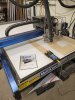
i am a brand new user of a MultiCam Graph-X-Cutter CNC machine (4ft X 8ft). I need help with EVERYTHING. LOL
I have searched to no avail for any training or helpful videos online so any of you experts want to chime in, please do so!!

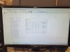
I am trying to cut 3/16" thick plexiglass letters. I believe I have set up my file (Toolpath) properly. My issue is the darn CNC starts to prepare to cut and it stays approx. 0.71" from the table top. I read that I need to calibrate the tool (in my case the spindle/router is tool #1) every time I change a bit. I follow the instructions that are in my manual but they are vague. Am I calibrating wrong? I set my top of plexi surface and then my max depth (MDF board / table top).
Why is it not calibrated properly? HELP HELP HELP

another thing is I set my SOFT home (Home 1) to start at a certain spot on the material and when it gets there the spindle drops down to the table surface where the 1/8" end mill bit almost hits the MDF where it might break the bit. How come it does that?
 

JBurton

Signtologist
Can ya snap a pic of the manual pages with the procedures?
Soft home should be where the machine thinks the corner of the material is if I'm remembering correctly. Luckily they haven't changed the buttons since 1987, so I could probably recall everything with a pic of the manual.

Or maybe someone else on here uses the machine and has the right answers already.
 

dasigndr

Premium Subscriber
JBurton, here are the photos
 

Attachments

  • 20230301_071449.jpg
    20230301_071449.jpg
    1.8 MB · Views: 129
  • 20230301_071429.jpg
    20230301_071429.jpg
    978.2 KB · Views: 124

JBurton

Signtologist
Sorry, I meant the pages for the instructions in the manual. I could probably give you some notes on what they are telling you to do and why.
 

dasigndr

Premium Subscriber
Sorry, I meant the pages for the instructions in the manual. I could probably give you some notes on what they are telling you to do and why.
I think we figured something out.
When calibrating the spindle (in my case it is tool #1), I have to set the grounding block on the black phenolic and NOT the top of the spoil board MDF.
Also I did a test cut using one of the preset files the installer had made and it cut exactly as required so I am thinking the issue is in my file. Doing more testing today. Will keep you all posted.
We use Enroute 23 for the file creation of the toolpaths. Maybe someone with more expertise on the Enroute software can chime in.
 

dasigndr

Premium Subscriber
Managed to cut a small plexiglass letter today. Created my file in enroute and it cut perfectly. I then went to nest my entire collection letters, then saved the file but when I goes to cut I am right back to the same problem i had in the initial post above. argggg can't figure out what I am doing wrong. Enroute users HELP!! should I create another post for enroute users as well?
 

JBurton

Signtologist
Just take your gcode files, rename them to pdf or whatever, and upload them here. I should be able to tell you exactly what is different between the first one and the second set.
 

dasigndr

Premium Subscriber
JBurton, here are the files.
 

Attachments

  • PROPERTIES - Copy.pdf
    3.9 KB · Views: 119
  • P-roperties - Copy.pdf
    6 KB · Views: 106
  • Devla-letter D - Copy.pdf
    3.2 KB · Views: 118

JBurton

Signtologist
So of the 3 different files, I see 3 different depths. Two files use the same tool, t9, and the third uses t10. All are labeled for 1/8" endmill.
This machine appears to be set up with the z axis inverted, negative values go up. As long as the machine is at least retracting between parts and descending when it's supposed to, even if it's not hitting the material, then this is just the way it's set up.


File delva- It's a big D, starts at -1.5 for rapid moves, then steps through in 4 passes, starting at -.925 and finishing at -.7.

File P-roperties - This one starts at -.5, then steps through in 2 passes, starting at .0938, final pass at .1875.

File Properties - This one starts up at -1.5, then steps through in 2 passes at -.895, final pass at -.79.

All of these could work depending on where you set z on the material. The file P-roperties seems to be the best, it would work if z0 was set to the material surface, it would travel above the material at .5", and it would plunge into the material half way and then all the way through a piece of 3/16" acrylic (btw, if you are cutting lexan, 3/16" as it's called actually measures out to .177")

You said you had one file that worked well, which one of these was it?
 

dasigndr

Premium Subscriber
So of the 3 different files, I see 3 different depths. Two files use the same tool, t9, and the third uses t10. All are labeled for 1/8" endmill.
This machine appears to be set up with the z axis inverted, negative values go up. As long as the machine is at least retracting between parts and descending when it's supposed to, even if it's not hitting the material, then this is just the way it's set up.


File delva- It's a big D, starts at -1.5 for rapid moves, then steps through in 4 passes, starting at -.925 and finishing at -.7.

File P-roperties - This one starts at -.5, then steps through in 2 passes, starting at .0938, final pass at .1875.

File Properties - This one starts up at -1.5, then steps through in 2 passes at -.895, final pass at -.79.

All of these could work depending on where you set z on the material. The file P-roperties seems to be the best, it would work if z0 was set to the material surface, it would travel above the material at .5", and it would plunge into the material half way and then all the way through a piece of 3/16" acrylic (btw, if you are cutting lexan, 3/16" as it's called actually measures out to .177")

You said you had one file that worked well, which one of these was it?
first off, thanks for the help. It is greatly appreciated.
File P-roperties was the one that cut correctly.

FYi; "
starts at -1.5 for rapid moves, then steps through in 4 passes, starting at -.925 and finishing at -.7.
" is foreign language to me. LOL
 

JBurton

Signtologist
That makes sense. Since p-roperties is the one that worked, I'll translate those comments a little more.

File P-roperties - This one starts at -.5, then steps through in 2 passes, starting at .0938, final pass at .1875.

So to translate a little more, the -.5 represents travel height (safe z, rapid height, non cutting height) basically when the machine is not cutting, but going to the next thing to cut. In this case it should have been about 1/2" above the sheet.
Then it went through in 2 passes, think of the surface of the material as 0, first pass went into the material at .0938", second pass went down all the way through to .1875" (3/16").

I'm pretty biased against enroute, it frustrates me how many steps you need just to make the simplest program. The otherside of the coin is that if you set it all up for your particular equipment, it will help you zoom through more difficult stuff with ease. I've been struggling to learn it, mostly due to distractions, but their knowledge base is really lacking and their support is as well. The very most frustrating part is the constant Adendo adverts in the sidebar every time it opens.
 

dasigndr

Premium Subscriber
So of the 3 different files, I see 3 different depths. Two files use the same tool, t9, and the third uses t10. All are labeled for 1/8" endmill.
This machine appears to be set up with the z axis inverted, negative values go up. As long as the machine is at least retracting between parts and descending when it's supposed to, even if it's not hitting the material, then this is just the way it's set up.


File delva- It's a big D, starts at -1.5 for rapid moves, then steps through in 4 passes, starting at -.925 and finishing at -.7.

File P-roperties - This one starts at -.5, then steps through in 2 passes, starting at .0938, final pass at .1875.

File Properties - This one starts up at -1.5, then steps through in 2 passes at -.895, final pass at -.79.

All of these could work depending on where you set z on the material. The file P-roperties seems to be the best, it would work if z0 was set to the material surface, it would travel above the material at .5", and it would plunge into the material half way and then all the way through a piece of 3/16" acrylic (btw, if you are cutting lexan, 3/16" as it's called actually measures out to .177")

You said you had one file that worked well, which one of these was it?
so explain to me WHY "
File delva- It's a big D, starts at -1.5 for rapid moves, then steps through in 4 passes, starting at -.925 and finishing at -.7.

" and does not come down to touch the material?

what causes these measurements?
 

JBurton

Signtologist
I believe these settings are defined in Enroute. We have it, but we have not utilized it any, just enough to become very frustrated with it, so I feel your pain there. My method is more tedious, and prone to user error, but it's much faster for me to just layer it in corel, export a dxf with Ecut, and generate the file in ncplot. While this is a "fine" way to make gcode, it would be doing you a disservice to steer you away from enroute. Honestly I'm surprised nobody has chimed-in in that regard. You may want to start a new post titled enroute help for more knowledgeable eyes to see. (Frankly I'll be watching closely in hopes that somebody can share a dumbed down overview of how to make a file in enroute! Enroute's info is all detailed but focused on individual functions, not much in the way of step by step process to go from start to finish.)

So ideally, you recall exactly what you did in creating the good file and repeat it on a new file, but obviously that's part of the reason for the thread!
 

dasigndr

Premium Subscriber
I believe we have found the issue!

When defining the plate I have to have the "Surface at top of plate" box checked. See photos attached.
I am not understanding why this needs to be checked. Searched for explanation on this and can't find any. Can anyone elaborate on this? thanks in advance!
 

Attachments

  • 20230309_095443.jpg
    20230309_095443.jpg
    2.5 MB · Views: 105
  • 20230309_095425.jpg
    20230309_095425.jpg
    2.4 MB · Views: 107

JBurton

Signtologist
Sure, with that checked, it considers the top of the material to be 0, everything below is a negative number, and everything above is a positive number. As far as I know, this is the preferred way that multicam's are set up, since you put the grounding block on the surface of the material to touch the bit to, it only knows where that surface starts, so as long as you are telling the machine how thick the material is, it should always cut through.
This is, in my opinion, the best way to set up, since you can eyeball the numbers and see that it is going down or up.

Short answer, because that is how the machine is set up in the factory.
 

Vassago

New Member
Always remember that the touch off plate sets zero. So when the cutter reaches the top of the plate, it hen subtracts the thickness of it and sets it to zero.

So if you place it on the spoil board, zero will be the top of that - (so the bottom of the substrate) - can be useful if you have variable thickness material - it'll always cut the same amount into the spoil board.
 
Top