• I want to thank all the members that have upgraded your accounts. I truly appreciate your support of the site monetarily. Supporting the site keeps this site up and running as a lot of work daily goes on behind the scenes. Click to Support Signs101 ...

3 Dimensional Geniuses - I need your help.

Andy D

Active Member
I have a metal fabricator that has been commissioned to build a large stainless steel sculpture.
He has a plasma cutter but is a older guy with no computer design experience, so I'm
going to help him set up the cut files and patterns.
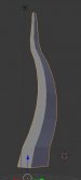
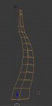
The part I need help with is 8' tall flames in a triangle & I'm not sure how to create
the three side so that they all follow the same shape of a flame that goes from around
2' wide at the base to about 2" wide at the top. There will be about 10 flames and they all
need to be different.
Here is a very basic illustration to help show what I mean:

upload_2019-12-6_13-50-33.png
 

James Burke

Being a grandpa is more fun than working
You need to find somebody with a solids modeling program such as Inventor or Solid Works.

The specific function is called "loft". It basically transitions from one cross section to another cross section through any given path.

Once the solid model is created, flat panels can be projected from the part to create cut files.

From the looks of the curves, I would assume he will also need to cut bend/roll templates to get the edges to match up for welding.

Looks like a fun project, and a great learning experience for you.


JB
 

Andy D

Active Member
You need to find somebody with a solids modeling program such as Inventor or Solid Works.
JB

Yes it is. I forgot what gauge, but he said he could hand roll it.
He said that if I can get the front edge right, then he could tack and grind the back section.
For the front two sides, if I set up two flames that are symmetrical but mirrored & he tacked all the high points and squeezed
in the low points, tacking as he went, would that follow the same shape so that his seam wouldn't be thick and thin?

Edited to say: actually you wouldn't mirror the front two sides shape, right?
 
Last edited:

Z SIGNS

New Member
That's a challenge.What James Burke said.Draw it in a modeling program and extract the pieces.Here is a quickie of what I'm talking about.
Another option if you have access to a 4 axis router would be to take the model slice it route it out of foam then clad it with thin ss sheet
 

Attachments

  • FLAME2.JPG
    FLAME2.JPG
    19.4 KB · Views: 210
  • FLAME.JPG
    FLAME.JPG
    22.7 KB · Views: 218

GAC05

Quit buggin' me
If you wanted to do it your self get a demo copy of Rhino 3D it will work for 90 days.
https://www.rhino3d.com/download
draw your shapes and curves in AI or Corel - import
position your bottom and top triangle close to the ends of the shape curve
From the Surface menu use Sweep one rail. It will ask for the path then the start and end shapes - enter
Then you can explode the the shape into the 3 sides
From surface - Unroll Developable Surface select and run once for each surface.
You will get the 3 sides flattened from there you can export the edge curves back to AI Draw to make your patterns.
3d-flame.jpg
 

Andy_warp

New Member
GAC05 has got it! If you haven't used cad or one of it's flavors it's a little tough to get used to the command prompt (the little white window at the top of my screen shot)
This is where you can input options to how you want your command to behave.

When you flatten the developable surfaces (this means its only curved in one direction...a non developable surface is curved in two directions...like an orange peel)
...be sure to say labels yes...sometimes when you flatten the surface...it will put it face down and you lose the orientation of which surface edges join where.

Edited to add: you see I use color coding just to keep it simple

If you have it flatten them with the labels, it gives you a roadmap on the original shape AND the flattened piece.

This shape isn't too bad since there is no rotation from the bottom cross section (big triangle) to the top cross section (little triangle)

The hardest part of this will be to design your base paths so the structures will be balanced and not want to lean or tip over!

Happy 3d'ing!
 

Attachments

  • flame.jpg
    flame.jpg
    638.7 KB · Views: 204

Andy D

Active Member
Thanks for everyone's input, I appreciate it.
I will probably end up using a 3-D program, but as a plan B, I'm used to creating these type of shapes manually,
so I came up with this Friday & meant to post it... Please take a look at it and see if you think it would work:

1. He would roll a 2” pipe using a pattern I print out.

2. He would weld that in a triangle steel base with a 2 1/8” hole.

3 He would tack different sizes steel triangle with offset holes

4 Using heavy duty poster paper, he would attach to one side, trace & then the other sizes

5 I digitize the pattern and turn it into a cutting file for him.


upload_2019-12-9_8-12-8.png
 

Andy_warp

New Member
Was totally going to suggest something like this!
You could probably just use plywood for your cross sections/spacers, no?

The cross sections will probably have the holes closer to center and will be at an angle perpendicular to the center support. You might want to key them too, so you don't get rotation in the surfaces.
 
Last edited:

Andy D

Active Member
Was totally going to suggest something like this!
You could probably just use plywood for your cross sections/spacers, no?

The cross sections will probably have the holes closer to center and will be at an angle perpendicular to the center support. You might want to key them too, so you don't get rotation in the surfaces.


The reason I was thinking steel was so he could tack them in place on the pole, plus he might need to tack thick wire down the three edges to better form the curve and to
help trace. I put the holes off center to create the curves on side C, you think that's too much?
 

FactorDesign

New Member
Fusion360 is going to be your best friend for this. It's free for startups or businesses making less than 100K from their 3D work. Wonderful modeling tools, sheet metal, and fabrication tools as well.
 

Andy_warp

New Member
The reason I was thinking steel was so he could tack them in place on the pole, plus he might need to tack thick wire down the three edges to better form the curve and to
help trace. I put the holes off center to create the curves on side C, you think that's too much?
Side C is going to have a curve already just from the other two sides.
I was saying plywood because it's NOT as permanent and can be adjusted.

I typically have to model stuff to visualize, so I may be wrong.
Maybe make a scale model with some pipe cleaners and cardboard to solve problems before you get there!
 
Top