• I want to thank all the members that have upgraded your accounts. I truly appreciate your support of the site monetarily. Supporting the site keeps this site up and running as a lot of work daily goes on behind the scenes. Click to Support Signs101 ...

FC7000-160 Cut Path Skewing

gamerxr72

New Member
Our FC7000-160 has begun to skew it's cut paths recently. This is a new problem.

Before someone suggest it, the pinch rollers are correctly adjusted. This isn't a material slant problem.

I've attached an example that shows the manner in which it cuts wrong.

I think it might be the reading laser, but I can't really be sure.
 

Attachments

  • badcutexample.jpg
    badcutexample.jpg
    38.4 KB · Views: 194

J Hill Designs

New Member
I'd say it's either the pinch rollers need adjusting, or there is a material slant problem...


Sorry, couldn't resist....It's friday...
 

bob

It's better to have two hands than one glove.
It's probably not the mark sensing tackle. If it were then all of the cuts should be off by the same offset.

It's probably not that the media is initially skewed, if it were the marks would not have been read. If the marks are read then any initial media skew would be mitigated by the software and/or firmware remapping each and every point to the proper location on the skewed media.

Since the marks were read, there is no error in the Y direction, the maximum error is at the point farthest from the origin, the point of maximum X and Y travel, and the the error represents a gain in media feed not a slippage, the question to answer is why is the plotter feeding more media on one side than the other?

Most interesting is that the cuts are only off in the X direction, not in the Y direction [assuming the picture is accurate]. If the media were dynamically skewing one would expect the cuts in both the X and Y directions to be off.

Interesting problem. There doesn't seem to be a ready solution that fits all of the evidence. It's almost as if something is adding a constant to the X position of the farthest mark. Highly doubtful.
 

Jim Doggett

New Member
It's perfect; you're spot-on. If you're still off, it's a tracking and not ARMS problem. You might have a bad pinch-roller .. or ???? I'd check with our support, if you got it from us ( www.signwarehouse.com/support/ ) They're there until 11 CST tonight.

Good luck,

Jim
 

907customs

New Member
Check all of your pinch rollers, if you ever cut punched material make sure there are none of the little circles stuck to any of the rollers, as this will change the diamater of the rollers, and cause the material to track incorrectly...It's happened to me a time or two.
 

gamerxr72

New Member
I am e-mailing graphtec america as well, but many times internet forums yield superior results.

Ive done a bit more testing to further define the problem. It's definitely a problem with the cutter itself, not the software I am using.

I started by printing a test file consisting of two rows of 50 cross-hairs. The overall size of the test area was about 11"x50".

Contradictory to my initial post, the vertical alignment is perfect. It is the horizontal alignment that begins to skew. At 7 SPEED the deviation was minimal but present. At 15 SPEED the deviation was great enough to ruin a real job. At 40 SPEED the deviation was more than half an inch over 11 linear inches of test material.


After reviewing the print I based my original example in my original post on, I realized I had the rotation wrong. If it is rotated 90 degrees clockwise it would then be correct.
 

bob

It's better to have two hands than one glove.
I am e-mailing graphtec america as well, but many times internet forums yield superior results.

Ive done a bit more testing to further define the problem. It's definitely a problem with the cutter itself, not the software I am using.

I started by printing a test file consisting of two rows of 50 cross-hairs. The overall size of the test area was about 11"x50".

Contradictory to my initial post, the vertical alignment is perfect. It is the horizontal alignment that begins to skew. At 7 SPEED the deviation was minimal but present. At 15 SPEED the deviation was great enough to ruin a real job. At 40 SPEED the deviation was more than half an inch over 11 linear inches of test material.


After reviewing the print I based my original example in my original post on, I realized I had the rotation wrong. If it is rotated 90 degrees clockwise it would then be correct.

Assuming then that the deviation is in the Y direction, carriage travel, and not the X direction, media travel. Does it gain or lose? In other words, does the carriage travel too far or not far enough?

Since the error seems to increase with speed, this would indicate some some sort of mechanical problem. Not that it couldn't be electronic, but unlikely.

How is the tension on the drive belt? That would be the first thing to check. Next would be all of the moving parts associated with that belt. Pulleys, drive mechanism, etc. Then perhaps a malfeasant drive motor and/or its control mechanism.
 

gamerxr72

New Member
It gains and looses differently based on what file I cut.

Most of the time it looses ground, but sometimes it gains.

The drive belt seems tensioned well enough. I don't see any sag and it stays in position on the gear when moved over the length of the cutting area.

At this point I'm suspecting the motor.
 

bob

It's better to have two hands than one glove.
It gains and looses differently based on what file I cut.

Most of the time it looses ground, but sometimes it gains.

The drive belt seems tensioned well enough. I don't see any sag and it stays in position on the gear when moved over the length of the cutting area.

At this point I'm suspecting the motor.

Interesting. A simple mechanical failure generally fails in the same way every time.

You might confirm that the carriage drive belt mechanism is solid by marking one tooth on the belt and the corresponding tooth on the drive wheel. No matter how much of what you cut the marked tooth on the belt and the drive should always line up right where you marked them.

I should think that the motor and perhaps it's control circuitry might well be the prime suspect. Hard to prove without instruments or merely replacing the suspect pieces.
 

gamerxr72

New Member
Interesting. A simple mechanical failure generally fails in the same way every time.

After preforming a reset on the cutter, nothing changed. I thought it might be a firmware error but apparently not.

I preformed more test cutting today.

It deviates in exactly the same manner every time for any given file, but the deviation seems inconsistent across different files.

As an example:
File1 has Graphtec ½" cut marks
File2 has Graphtec ½" interval cut marks

File1 deviates left
File2 deviates right

Of course, that is just an example. The only right-deviating test I had used interval cut marks. Every other file deviates left.
 

gamerxr72

New Member
After talking to Graphtec America and a tech Reece Supply, the problem is apparently the pulley/gear on the right side of the machine.

The tech is going to be out of town all week apparently, but I do have part numbers. Is this something we could do ourselves?

We've replaced parts on our Mutoh's, so we aren't incompetent when it comes to repairing our equipment, but we are also unfamiliar with cutters. If there is specialized equipment involved in fixing or calibrating, then we won't do it.
 

chrisphilipps

Merchant Member
Replacing the Pulley itself isn't hard to do, the question is if they are going to send out a replacement Pen Board or just parts that need to be soldered onto the Pen Board. Graphtec has sent them both ways. When you update the Pulley you will either have to replace or solder parts onto the Pen Board, if you don’t feel comfortable in soldering then you might want to wait for a tech.
 

Compilla

New Member
After talking to Graphtec America and a tech Reece Supply, the problem is apparently the pulley/gear on the right side of the machine.

it.
You should be able to replace that pulley.


I though it was a X axis issue rather than a Y axis issue,what kind of testing
they had you do to determine it was a Y pulley issue ?
 

gamerxr72

New Member
Replacing the Pulley itself isn't hard to do, the question is if they are going to send out a replacement Pen Board or just parts that need to be soldered onto the Pen Board. Graphtec has sent them both ways. When you update the Pulley you will either have to replace or solder parts onto the Pen Board, if you don’t feel comfortable in soldering then you might want to wait for a tech.

I don't see any of the parts in question connecting to any board, but both you and the technician at Reece hinted that a board replacement will be necessary.

Why is this?

The only parts the guy at Graphtec told me the #'s for were:
Y pulley Part Number 792700705
Pin Part Number 772126660

You should be able to replace that pulley.


I though it was a X axis issue rather than a Y axis issue,what kind of testing
they had you do to determine it was a Y pulley issue ?

In my original post, I was wrong about the direction as I was basing my information off of a failed cut and I had the rotation wrong. The skewing is entirely on the horizontal axis.

By the way, I've always thought that a Y-Axis was vertical (forward and back in this case) and an X-Axis was horizontal. Am I just wrong, or is this something that graphtec does?

Even the guy at graphtec called it a Y-Pulley.

Just for clarification, we are talking about the pulley that moves the carriage belt left & right, aren't we?

As for the test, I preformed enough test cuts to clarify the problem apparently, as I described what the problem was and the guy just seemed to know.

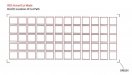
After pen-plotting 15 rows of 29 1"x1" squares (which was supposed to make a grid of squares), each row is shifted slightly more to the left of the row that precedes it, with the final row being the most shifted.

For cut-only vinyl this isn't a problem usually. But for contour cutting, it will ruin any job that has more than 2 rows of decals.
 

Compilla

New Member
Got you gamerxr72 !!

The initial picture confused the hell out of me.

Yes, the Y axis pulley you have it is made of plastic and after a few years the plastic shaft separates. The new pulley stile it is aluminum made and should last longer.

Pretty easy to replace, just like any other machine, you loose the belt tension on the left hand side in order to replace the belt.

:thumb:
 
Top