artbot
New Member
to anyone that has this sort of printer (H650, H652's may be the same),
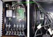
i'm installing a daytona H700 and have the power run. everything seems fine power-wise. then i see this power supply inside the ink tank area that seems to go to the ink control board with a chord to itself. is this supposed to be independently plugged in? i've attached several photos and diagrams to aid in the communication.
in the photo titled white ink pump question- you see on the top left a green oval. this is where the red/black line comes through the other side to this small break out box thing. you can trace the two lines breaking out to two 24v power supply plug ins on the ink control box. does this mean that my ink control is "un-powered".
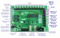
in the photo titled missing power supply hookup- on the left you can see a green and pink highlighted line. these are the two wires coming from the break out box.
thanks in advance.
i'm installing a daytona H700 and have the power run. everything seems fine power-wise. then i see this power supply inside the ink tank area that seems to go to the ink control board with a chord to itself. is this supposed to be independently plugged in? i've attached several photos and diagrams to aid in the communication.
in the photo titled white ink pump question- you see on the top left a green oval. this is where the red/black line comes through the other side to this small break out box thing. you can trace the two lines breaking out to two 24v power supply plug ins on the ink control box. does this mean that my ink control is "un-powered".
in the photo titled missing power supply hookup- on the left you can see a green and pink highlighted line. these are the two wires coming from the break out box.
thanks in advance.