• I want to thank all the members that have upgraded your accounts. I truly appreciate your support of the site monetarily. Supporting the site keeps this site up and running as a lot of work daily goes on behind the scenes. Click to Support Signs101 ...

Gerber Sabre 408……HELP

CNCguru

New Member
My machine has ran flawless for over 13yrs. One evening I walked out to do a job & got a contineus beep & a message stating x axis error/encoder. Shortly after I noticed it burned out a capacitor on my main board. Anyone out there have any suggestions. I got a new capacitor & w/ have it replaced but any suggestions on how & why I had the experience.

Thank u
 

Attachments

  • image.jpg
    image.jpg
    1 MB · Views: 159

netsol

Premium Subscriber
You hAd the experience because electrolytic capacitors go bad over time. Go on eBay and buy a ESR meter. Less than than $35. Check every electrolytic. On the board. Replace any that test bad. It's great technology. Tests in circuit, power off. BEFORE THEY GO BAD, they get weak. I am surprised the tech that changed the cap for you didn't recommend this.
 

CNCguru

New Member
You hAd the experience because electrolytic capacitors go bad over time. Go on eBay and buy a ESR meter. Less than than $35. Check every electrolytic. On the board. Replace any that test bad. It's great technology. Tests in circuit, power off. BEFORE THEY GO BAD, they get weak. I am surprised the tech that changed the cap for you didn't recommend this.
Thank you for ur advice. I have had 3 capacitors go out on me since 2005. I w/ deff get a fester
& go thru them all. Would that also be the reason for my x-axis/encoder fault?
 

CNCguru

New Member

netsol

Premium Subscriber
Very possibly.
as electrolytics fail you get ‘noise’ on what should be nice clean dc voltage.
it plays hell with every circuit, but, some more than others.

REMEMBER. POWER OFF, unplug powe & wait ten minutes
protects delicate electronics & with larger caps, protects YOU from a nasty shock
 

Vassago

New Member
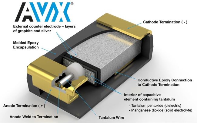
Unfortunately the capacitor shown isn't an electrolitic cap.. It looks like a tantalum cap - these are far more sensitive to over voltage than electrolytics. I'd guess that the psu is failing which probably does have electrolytics in them.. Their ESR value has probably changed and ac ripple is getting through to the main board.

Check the psu and replace all the electrolytics - they'll be aluminium tubes with Heatshrink sleeves on them - they don't need to have popped to be bad.

A simple check is to put a meter in ac mode on the dc rails - it'll how show much ac is present (should be very very low).


The picture it shows is a modern surface mount cap, but it's the same as the older leaded versions.
 

Vassago

New Member
The encoder fault is quite likely either over voltage or ac ripple.

I'd change the psu caps ASAP before you get a big voltage spike that takes out everything.
 

netsol

Premium Subscriber
I will, say, though, the 1980’s/1990’s vintage electronics that Gerber used are
resiliant as hell. Much like my Gerber plotters & Edge’s the biggest problems besides caps is
poor connections at plug ins. They held up much better to surges than most other equipment
 

Vassago

New Member
I will, say, though, the 1980’s/1990’s vintage electronics that Gerber used are
resiliant as hell. Much like my Gerber plotters & Edge’s the biggest problems besides caps is
poor connections at plug ins. They held up much better to surges than most other equipment
Exactly.. Poor earth's, loose connections cause massive frustrating issues..

Caps ageing in psus is a big issue as they can blow the lot, servo drives usually have the same issues..

Prevention is better than waking up to everything in bits.. Not an easy task though..
 

netsol

Premium Subscriber
until the 1980's LOW VOLTAGE ELECTROLYTICS lasted almost forever, it seemed.
then the japanese learned how to make them cheaper
if you were servicing consumer electronics, you did almost nothing other than changing caps and reaching for the ESR meter
the way the caps were rated changed. smaller caps with the same rating.
everything ran hotter and you could see the electrolyte run out through the vent holes in the caps
 

CNCguru

New Member
Unfortunately the capacitor shown isn't an electrolitic cap.. It looks like a tantalum cap - these are far more sensitive to over voltage than electrolytics. I'd guess that the psu is failing which probably does have electrolytics in them.. Their ESR value has probably changed and ac ripple is getting through to the main board.

Check the psu and replace all the electrolytics - they'll be aluminium tubes with Heatshrink sleeves on them - they don't need to have popped to be bad.

A simple check is to put a meter in ac mode on the dc rails - it'll how show much ac is present (should be very very low).


The picture it shows is a modern surface mount cap, but it's the same as the older leaded versions.
Thank you for ur knowledge. I w/ check that as well. This is all new to me & I am learning as we go. So in the past I have had them just replace the burnt cap, but I w/ take ur advice & replace all. The unit is from 2005 & we are located in Florida w/ TONS of humidity.
 

fdarling

New Member
I recently helped someone track down a similar problem, the issue in their case turned out to be a faulty limit switch. The limit switches inhibit the amplifier from allowing the servo to move further in the direction of the switch, but if you aren't actually on a limit it confuses the controls because it can't move in a particular direction when it commands it. The error message is sometime a bit cryptic, in my opinion it should make it clear that the amplifier is inhibited due to the limit switch (information it also has), and not randomly inhibited for no reason. You can check the limit switch states with a multimeter on certain pins of certain resistors on the motherboard.

That being said, sometimes the problem is more complicated, like a burned out pin on a chip on the motherboard. I know what pins to probe to verify limit switch and fault signals are propagating correctly, and if you are still struggling with this I can give phone support to help you track it down...
 

CNCguru

New Member
I recently helped someone track down a similar problem, the issue in their case turned out to be a faulty limit switch. The limit switches inhibit the amplifier from allowing the servo to move further in the direction of the switch, but if you aren't actually on a limit it confuses the controls because it can't move in a particular direction when it commands it. The error message is sometime a bit cryptic, in my opinion it should make it clear that the amplifier is inhibited due to the limit switch (information it also has), and not randomly inhibited for no reason. You can check the limit switch states with a multimeter on certain pins of certain resistors on the motherboard.

That being said, sometimes the problem is more complicated, like a burned out pin on a chip on the motherboard. I know what pins to probe to verify limit switch and fault signals are propagating correctly, and if you are still struggling with this I can give phone support to help you track it down...
Thank u very much on ur knowledge. I am currently replacing some burnt capacitors on my board. I have had this happen two other times but it always has been replace the caps & I was back up & running. This time has been different. I have gotten an error on the x-axis & it just continuously beeps letting u know something is wrong. I am going to test the e-stops to check for anything there. I have attached some pics of the board & the cap.

Thank u, Glenn
 

Attachments

  • IMG_1494.jpeg
    IMG_1494.jpeg
    2.5 MB · Views: 104
  • IMG_1493.jpeg
    IMG_1493.jpeg
    921.4 KB · Views: 117
  • IMG_1492.jpeg
    IMG_1492.jpeg
    1.4 MB · Views: 122

fdarling

New Member
The first thing I would do is test the power supply voltages. I attached a photo circling the points you can probe with a multimeter, the right-most point would be the motherboard screw that is grounded, where you should put the negative (black) lead of the multimeter. The positive (red) lead of the multimeter should be on the circled points on the resistors corresponding to the respective voltage presence indicator LEDs.

Let me know what those voltages read...
 

Attachments

  • Gerber_Motherboard_Voltage_Test_Points.jpg
    Gerber_Motherboard_Voltage_Test_Points.jpg
    86.3 KB · Views: 78
Top