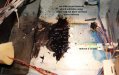
Mission accomplished.
It took less than an hour, even though I had some cleaning up to do. Found a couple screws inside as well, mixed into the blob. They are probably the ones I noticed missing when I began service.
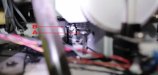
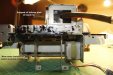
In order to help others who may at some point need to address the same servicing, I have attached a few reference images to help demystify what you may encounter.
All in all, it was quite easy to do. And I would suggest not removing those two long screws on the left noted as 'A' and 'B' in the previous images posted. I believe they are for leveling, and that's what I had figured in advance, so used a small level (bubble) for registration before I had removed them so that I could get them set back to where they belong.
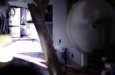
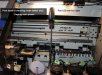
1) Get the head into cleaning position (far left).
2) Disconnect main power.
3) You will need to pull the rubber drain tube up and out the top first by removing the small metal clamp held by a single #2 Phillips. Be careful of dripping. Use paper towel and tape to block the end of the tube if necessary.
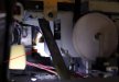
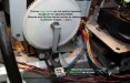
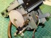
4) There are 4 connectors/sockets to be disconnected. Two at the front (noted in images below) and two which will be discovered along the right side of the assembly. Start with the two at the front.
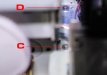
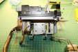
5) Remove the two fastener/mounting screws (on the right; 'C' and 'D') from assembly to frame, then, gently move the assembly to the left in order to disconnect the furthest of the 4 connectors/sockets.
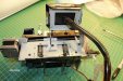
6) Having done so, you should easily be able to clear everything and pull the unit out from the printer.
7) Installation is just the reverse of that described above.
*Special thanks goes out to 'Ragnabrok' for the advance notice and recommendations before I got into it
")
Mods: if this information is worthy, please move or copy into the do it yourself section.
============================